Two-link anaytical method - Worksheet
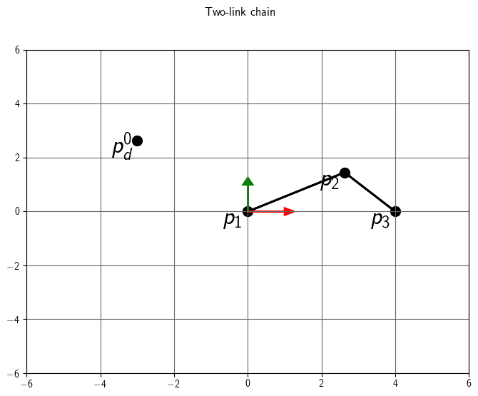
Suppose we have the 2-link chain below. We wish to compute rotations for
joint 1 and joint 2 so that joint 3's position is located at a target \(p_d\).
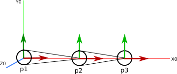
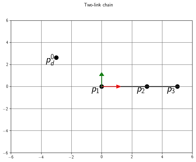
The root joint position p1 is located at the origin.
The next joint position p2 is offset from p1 by (3,0,0)T
The next joint position p3 is offset from p2 by (2,0,0)T
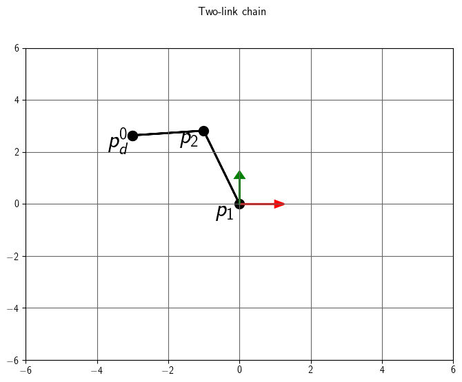
The target position is \(p_d^0 = (-3, \sqrt{7}, 0)^T\).
This approach has two parts.
- Length: In the first part, we use the law of cosines to
get the desired length between the joint 1 and joint 3.
- Orientation: In the second part, we
compute the orientation for joint 1 that points the limb towards the desired
position. In class, we covered two methods we can use for this.
- Polar coordinate method In the first method, we align the limb with
the x-axis and then compute heading and elevation rotations.
- Angle/axis method In the second method, we will compute a single
angle/axis rotation.
Kinematic equation
To begin, let's write the kinematic equation for this joint chain.
\[
\begin{bmatrix}
p_3^0 \\
1
\end{bmatrix}
=
\begin{bmatrix}
R_1^0 & d_1^0 \\
0 & 1
\end{bmatrix}
\begin{bmatrix}
R_2^1 & d_2^1 \\
0 & 1
\end{bmatrix}
\begin{bmatrix}
R_3^2 & d_3^2 \\
0 & 1
\end{bmatrix}
\begin{bmatrix}
0 \\
1
\end{bmatrix}
\]
where
- \(R_i^j\) is the local rotation for each joint i (e.g. with respect to its parent joint j)
- \(d_i^j\) is the local offset for each joint i from its parent
To start, each \(R_i^j = I \). We want \( p_3^0 \) to equal \( p_d^0 \)
Step 1: Length
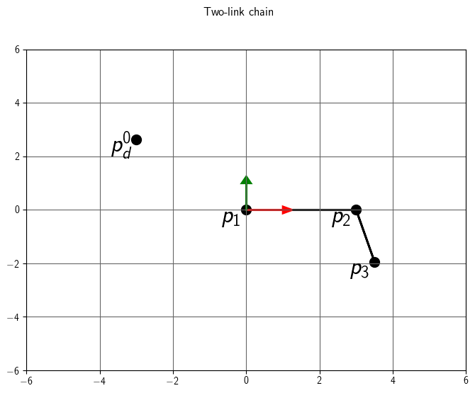
We will compute the rotation for joint 2 that makes the length
between \(p_3^0\) and \(p_1^0\) match the length between \(p_3^0\) and \(p_d^0\).
Because our joint chain extends along the x axis, this rotation will
be around z. Let's call this rotation \(\theta_{2z}\).
Recall that the law of cosines gives us the relationship between the angle
at joint 2 and distance between \(p_3^0\) and \(p_1^0\).
\[
r^2 = (l_1)^2 + (l_2)^2 - 2(l_1)(l_2)\cos(\phi)
\]
where
- \(l_1\) is the distance between joint 1 and joint 2
- \(l_2\) is the distance between joint 2 and joint 3
- r is the desired distance between joint 1 and the target
- \(\phi\) is the desired interior angle at joint 2
Once we have \(\phi\), we can compute the corresponding rotation angle at
joint 2 as \(\theta_{2z} = \phi - \pi\). With this configuration, our final
rotation will be \(R_z(\theta_{2z})\)
Let's compute the rotation for joint 2.
- What is desired length r between joint 1 and the target?
\[
r = ||p_d^0 - p_1^0|| = 4
\]
- What is l1?
because lengths cannot change, we can simply compute the magnitude of the
offset between joint 2 and joint 1.
\[
||d_2^1|| = 3
\]
- What is l2?
The length will be the magnitude of the offset between joint 3 and joint 2.
\[
||d_3^2|| = 2
\]
- What is \(\phi\)?
\[
\cos(\phi) = \frac{r^2 - (l_1)^2 - (l_2)^2}{-2(l_1)(l_2)} = \frac{(4)^2 - (3)^2 - (2)^2}{-2(3)(2)} = -0.25\\
\]
\[
\phi = \arccos(-0.25) = 1.8235 \quad \text{radians}
\]
- What is \(\theta_{2z}\)?
\[
\theta_{2z} = \phi - \pi = -1.3181 \quad \text{radians}
\]
- Verify that \(p_3^0\) and \(p_1^0\) are the correct distance apart by plugging
\(R_z(\theta_{2z})\) into the kinematic equation for these joints.
\[
\begin{bmatrix}
p_3^0 \\
1
\end{bmatrix}
=
\begin{bmatrix}
I & d_1^0 \\
0 & 1
\end{bmatrix}
\begin{bmatrix}
R_z(\theta_{2z}) & d_2^1 \\
0 & 1
\end{bmatrix}
\begin{bmatrix}
I & d_3^2 \\
0 & 1
\end{bmatrix}
\begin{bmatrix}
0 \\
1
\end{bmatrix}
\]
The new global position of joint 3 is (3.5, -1.93649, 0)T, so
the distance is
\[
||p_3^0 - p_1^0|| = 4
\]
Step 2: Orientation - Polar coordinate method
Now that \(p_1^0\) and \(p_3^0\) are the correct distance apart, we need to
compute the rotation for joint 1 that points the vector \(p_3^0 - p_1^0\) towards
\(p_d^0\).
Step 2a: Point the limb along the x-axis
- What is the angle \( \theta_{1z}\)?
\[
\sin(\theta_{1z}) = \frac{-(l_2) \sin(\theta_{2z})}{r}
= \frac{-(2)(\sin(-1.3181))}{4} = 0.48412\\
\]
\[
\theta_{1z} = \arcsin(0.48412) = 0.50536 \quad \text{radians}
\]
- Verify that the limb now points along the x axis by pluggin in \(\theta_{1z}\) into the kinematic equation.
\[
\begin{bmatrix}
p_3^0 \\
1
\end{bmatrix}
=
\begin{bmatrix}
R_z(\theta_{1z}) & d_1^0 \\
0 & 1
\end{bmatrix}
\begin{bmatrix}
R_z(\theta_{2z}) & d_2^1 \\
0 & 1
\end{bmatrix}
\begin{bmatrix}
I & d_3^2 \\
0 & 1
\end{bmatrix}
\begin{bmatrix}
0 \\
1
\end{bmatrix}
\]
The new global position of joint 3 is (4, 0, 0)T. Because joint 1 is located at the origin, we can see that the direction \( p_3^0 - p_1^0 \) points along the x-axis.
Step 2b: Point the limb to the target
Compute the euler angles YZX for p1 which points towards
pd. In this formulation the heading will be used to construct a Y
rotation and the elevation will be used to construct a Z heading. The X
rotation is zero because this only casues the limb to twist, so it doesn't
affect the position of joint 3.
- What is the heading \(\beta\)?
\[
\beta = \text{atan2}(p_{dz}^0, p_{dx}^0) = \text{atan2}(0, -3) = \pi
\]
- What is the elevation \(\gamma\)?
\[
\gamma = \arcsin(\frac{p_{dy}^0}{r}) = \arcsin(\frac{\sqrt{7}}{4}) = 0.72272
\]
- Verify that the \(p_3^0\) is at \(p_d^0\) by plugging in the rotation for joint 1 into the kinematic equation.
\[
\begin{bmatrix}
p_3^0 \\
1
\end{bmatrix}
=
\begin{bmatrix}
R_{yzx}(0, \beta, \gamma) R_z(\theta_{1z}) & d_1^0 \\
0 & 1
\end{bmatrix}
\begin{bmatrix}
R_z(\theta_{2z}) & d_2^1 \\
0 & 1
\end{bmatrix}
\begin{bmatrix}
I & d_3^2 \\
0 & 1
\end{bmatrix}
\begin{bmatrix}
0 \\
1
\end{bmatrix} \\
=
\begin{bmatrix}
R_y(\beta) R_z(\gamma) R_z(\theta_{1z}) & d_1^0 \\
0 & 1
\end{bmatrix}
\begin{bmatrix}
R_z(\theta_{2z}) & d_2^1 \\
0 & 1
\end{bmatrix}
\begin{bmatrix}
I & d_3^2 \\
0 & 1
\end{bmatrix}
\begin{bmatrix}
0 \\
1
\end{bmatrix} \\
\]
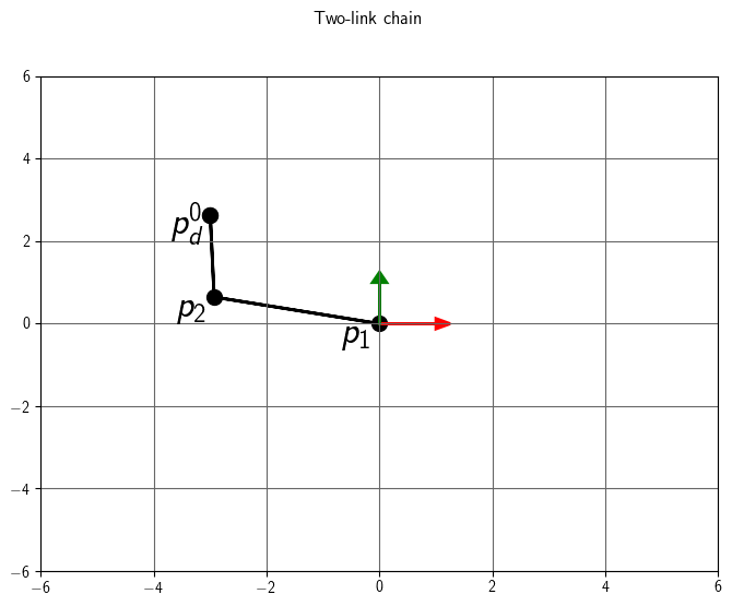
The global position of joint 3 in now (-3, \(\sqrt{7}\), 0)T.
Step 2: Orientation - angle/axis method
Now that \(p_1^0\) and \(p_3^0\) are the correct distance apart, we need to
compute the rotation for joint 1 that points the vector \(p_3^0 - p_1^0\) towards
\(p_d^0\).

This time, let's use the angle/axis computation from our CCD algorithm.
When using this approach, the nudge factor is one. In this context, we wish to
solve directly for the full angle. Because this method computes a
relative angle, it often looks better if we reset the joint rotation to
identity before computing the angle/axis. (Watch out: we do not want to reset
to identity when implementing the CCD algorithm!)
- What is the limb direction r0?
\[
r^0 = p_3^0 - p_1^0 =
\begin{bmatrix}
3.5 \\
-1.93649 \\
0
\end{bmatrix}
-
\begin{bmatrix}
0 \\
0 \\
0
\end{bmatrix}
=
\begin{bmatrix}
3.5 \\
-1.93649 \\
0
\end{bmatrix}
\]
- What is the error direction e0?
\[
e^0 = p_d^0 - p_3^0 =
\begin{bmatrix}
-3 \\
\sqrt{7} \\
0
\end{bmatrix}
-
\begin{bmatrix}
3.5 \\
-1.93649 \\
0
\end{bmatrix}
=
\begin{bmatrix}
-6.5 \\
4.58224 \\
0
\end{bmatrix}
\]
What is the direction \(r^0 \times e^0 \)?
\[
r^0 \times e^0 =
\begin{bmatrix}
0 \\
0 \\
3.45065 \\
\end{bmatrix}
\]
What is the angle of rotation \(\phi \) and axis of rotation \(u^0\)?
\[
\phi = \text{atan2} (|| r^0 \times e^0 ||, r^0 \cdot r^0 + r^0 \cdot e^0) = 2.9242 \quad \text{radians}
\]
\[
u^0 = \frac{r^0 \times e^0}{|| r^0 \times e^0 ||} =
\begin{bmatrix}
0 \\
0 \\
1
\end{bmatrix}
\]
Verify that the \(p_3^0\) is at \(p_d^0\) by plugging in the rotation for joint 1 into the kinematic equation.
\[
\begin{bmatrix}
p_3^0 \\
1
\end{bmatrix}
=
\begin{bmatrix}
R_u(\phi) & d_1^0 \\
0 & 1
\end{bmatrix}
\begin{bmatrix}
R_z(\theta_{2z}) & d_2^1 \\
0 & 1
\end{bmatrix}
\begin{bmatrix}
I & d_3^2 \\
0 & 1
\end{bmatrix}
\begin{bmatrix}
0 \\
1
\end{bmatrix}
\]
The global position of joint 3 in now (-3, \(\sqrt{7}\), 0)T.
